
Ahoj Woyto,
tak jak, nějaký progress? ;-)
Heleď chtěl jsem se zeptat:
V prvním příspěvku píšeš že "potřebujeme" Arduino Uno, tak jsem koukal na Ali a nevím, jestli je lepší koupit raději celý kit i s různýma doplňkama, který pravděpodobně nikdy nepoužiju:
https://www.aliexpress.com/item/NEWEST-RFID-Starter-Kit-for-Arduino-UNO-R3-Upgraded-version-Learning-Suite-With-Retail-Box/32714696336.html?spm=2114.search0104.3.16.667f3b7fNGNOl6&ws_ab_test=searchweb0_0,searchweb201602_3_10152_10151_10065_10344_10068_5722815_10342_10343_10340_5722915_10341_5722615_10696_10084_10083_10618_10304_10307_10302_5722715_10059_10534_100031_10103_441_10624_10623_10622_5722515_10621_10620-10621,searchweb201603_25,ppcSwitch_5&algo_expid=4ad2d172-1562-41e7-969d-279e72a3365f-2&algo_pvid=4ad2d172-1562-41e7-969d-279e72a3365f&transAbTest=ae803_4&priceBeautifyAB=0
Anebo bohatě stačí "základní" sada, která podle mě obsahuje nejnutnější výbavu pro zkoušení a programování:
https://www.aliexpress.com/item/Starter-Kit-UNO-R3-mini-Breadboard-LED-jumper-wire-button-for-Arduino-compatile-Free-Shipping/32591389250.html?spm=2114.search0104.3.45.667f3b7fNGNOl6&ws_ab_test=searchweb0_0,searchweb201602_3_10152_10151_10065_10344_10068_5722815_10342_10343_10340_5722915_10341_5722615_10696_10084_10083_10618_10304_10307_10302_5722715_10059_10534_100031_10103_441_10624_10623_10622_5722515_10621_10620,searchweb201603_25,ppcSwitch_5&algo_expid=4ad2d172-1562-41e7-969d-279e72a3365f-6&algo_pvid=4ad2d172-1562-41e7-969d-279e72a3365f&transAbTest=ae803_4&priceBeautifyAB=0
Já osobně se přikláním spíše ke druhé variantě - jednak kvůli ceně a jednak proto že bych pak měl doma spoustu nevyužitých součástek.
Spíš mi jde ale o to, jestli třeba ten "kit" z první varianty neobsahuje něco, co bych musel ke druhé variantě doobjednávat zvlášť. To bych se na to vykašlal a koupil rovnou tu větší sadu...

Re: Arduino
Kit si vyber jakej se ti hodi. Ja mel jinej kit.
Kazdopadne uno s breadboardem na vyvoj a nano na finalni zapojeni.
Ja ted s arduinem nic nedelal. MP3 funguje a ja si ted hraju s 3D tiskarnou.
Kazdopadne uno s breadboardem na vyvoj a nano na finalni zapojeni.
Ja ted s arduinem nic nedelal. MP3 funguje a ja si ted hraju s 3D tiskarnou.
Re: Arduino
Nasel jsem tenhle zajimavej projekt.
https://github.com/TheDIYGuy999/Rc_Engine_Sound
https://www.youtube.com/watch?v=c6SuleJacWg
Tedka koukam do kodu, jestli by tan neslo vpasovat nejaka svetla a rizeni navijaku.
https://github.com/TheDIYGuy999/Rc_Engine_Sound
https://www.youtube.com/watch?v=c6SuleJacWg
Tedka koukam do kodu, jestli by tan neslo vpasovat nejaka svetla a rizeni navijaku.
Re: Arduino
Tak jsem se trochu rozkoukal v tom kodu a zacal s vlastnim navrhem.
Audio je vazane jen na 1 kanal. Coz je prima. Z kodu pouziju 90%. Jen vyhodim testovaci funkce a premistim pin vystupu repro a vstupu druheho kanalu.
Necham asii jeho detekci ztraceneho signalu. Jen do toho pridam kod pro vystrazna svetla.
Co tam ma dale je digitalni potenciometr MCP4131, ktery podle popisu dava zvuku motoru vetsi hloubku. Neni nutne aby tam byl, funguje to u bez nej. Ale necham ho tam. Jeho zapojeni zabira 6 pinu z toho 2 pouzival pro napajeni. Tyhle 2 piny Uvolnim pri jiny ucel.
Vstup v mem pripade bude 5 kanalu.
Rizeni/blinkry, Plyn, tlacitko svetla, navijak 1, navijak 2.
Na strane vystupu budou 2piny blinkry, 1 pin svetla, 1 pin rampa, 1 pin zpatecka, 4 piny navijaky. No a pokud nevyhodim ten digitalni potenciometr, tak jsem s funkcema skoncil, protoze dosly vystupy :D
Na rizeni obou motoru navijaku pouziju desku s L298N https://www.aliexpress.com/item/3297730 ... 4c4dzpvGhD
Jako zesilovac zkusim pouzit PAM8403 co doporucuje. Nema regulaci hlasitosti, tak uvidim zda ho nevymenim za neco jineho. https://www.aliexpress.com/item/3262001 ... 4c4dzpvGhD
No a pak bude asi sranda nejvetsi. Najit repracek kteremu nebude vadit voda a bahno :D
Re: Arduino
No tak už si pár dní hraju s kodem. Podle papírů co mám před sebou jsem odstranil zhruba polovinu původního kódu a zvuk to stále generuje. :D
Mělo by být odstraněno snad vše co se týká SPI. Pak zmizela testovací funkce pro potenciometr (servotester to řeší) . Detekci ztráty signálu jsem zjednodušil a místo vypnutí motoru to bude bublat na volnoběh. A servo vstup přestěhoval na A2.
Pak jsem to začal krmit testovacím kódem pro blinkry a navijáky.
Piny plánuji užít takto:
A0 Input - jumper pro režim svícení
A1 Input - RC prijimac CH1
A2 Input - RC prijimac CH2 (v původním programu D2)
A3 Input - RC prijimac CH3
A4 Input - RC prijimac CH4
A5 Input - RC prijimac CH5
A6 volný
A7 volný
D0 Output - Světlomety
D1 Output - Světelná rampa
D2 Output - Zpátečka
D3 Output - Momentálně Repro. (Pry by mělo jít přesunout na D11 Potom by zde byli brzdová světla)
D4 Output - Digitální potenciometr
D5 Output - Digitální potenciometr
D6 Output - Digitální potenciometr
D7 Output - Naviják 1
D8 Output - Naviják 1
D9 Output - Naviják 2
D10 Output - Naviják 2
D11 Output - Brzdová světla (pokud nepujde přehodit repro)
D12 Output - Levý Blinkr
D13 Output - Pravý Blinkr
Při tom jsem zjistil nemilou věc. Digitalni piny 7-12 nemůžu ovládat.
A narazil jsem na vtipnou věc. Signál pro generátor beru z pinu A2.
Pokud ale přivedu signál současně na A1 a A3 tak generování zvuku také funguje. WTF? Tipuju, že něco čachruje s registrem vstupu, tam a zpět.
Řekl bych, že vetšina problémů bude zakopaná v setupPCM. Bohuzel to je moje první setkání s přerušením. Takže by se mi hodilo kdyby na to kouknul někdo kdo se vyzná a nasměroval mě správným směrem.
Kód: Vybrat vše
/*
      This code was quick and dirty, based on a PCM audio example in the
      arduino playground: http://playground.arduino.cc/Code/PCMAudio

      It's been heavely modified for use with RC to generate something that's
      a bit like an engine sound. I've started work on making the program
      readable, still some to do though.
      https://github.com/BeigeMatchbox/mojoEngineSim/blob/master/README.md

      Enhancements, done by TheDIYGUY999 in january 2017: https://github.com/TheDIYGuy999/Rc_Engine_Sound
        - more sounds added,
        - also works on a 8MHz MCU, but not in servo throttle mode
*/

// All the required settings are done in settings.h!
#include "settings.h" // <<------- SETTINGS

const float codeVersion = 1.2; // Software revision

/*/Pins for lights
#define LIGHTS 0
#define LIGHTBAR 1
#define REVERSE 2
#define BRAKE 3
*/

//Pins for two winches
#define WINCH1WIND 7
#define WINCH1UNWIND 8
#define WINCH2WIND 9
#define WINCH2UNWIND 10

//Pins for turn signals
#define RIGHTTURN 12
#define LEFTTURN 13


// Stuff not to play with! ----------------------------------------------------------------------------
#define SPEAKER 3                               // This is kept as 3, original code had 11 as option, but this conflicts with SPI
volatile uint16_t currentSmpleRate = BASE_RATE; // Current playback rate, this is adjusted depending on engine RPM
boolean audioRunning = false;                   // Audio state, used so we can toggle the sound system
boolean engineOn = true;                        // Signal for engine on / off
uint16_t curVolume = 0;                         // Current digi pot volume, used for fade in/out
volatile uint16_t curEngineSample;              // Index of current loaded sample
uint8_t  lastSample;                            // Last loaded sample
int16_t  currentThrottle = 0;                   // 0 - 1000, a top value of 1023 is acceptable
volatile int16_t pulseWidthCH2 = 0;                // Current pulse width for CH2 Throttle
#define FREQ 16000000L                          // Always 16MHz, even if running on a 8MHz MCU!

int16_t pulseMaxNeutral; // PWM throttle configuration storage variables
int16_t pulseMinNeutral;
int16_t pulseMax;
int16_t pulseMin;
int16_t pulseMaxLimit;
int16_t pulseMinLimit;

unsigned int pulseWidthCH1 = 0;                // Current pulse width for CH1 Steering
                                               //CH2 In stuff not to play with!
unsigned int pulseWidthCH3 = 0;                // Current pulse width for CH3 C button for lights
unsigned int pulseWidthCH4 = 0;                // Current pulse width for CH4 Winch 1
unsigned int pulseWidthCH5 = 0;                // Current pulse width for CH5 Winch 2

unsigned int CH1 = 0;                // For cleaning up pulse value
unsigned int CH2 = 0;                 // Used for signal loss detection
unsigned int CH3 = 0;                // Current pulse width for CH3 C button for lights
unsigned int CH4 = 0;                // Current pulse width for CH4 Winch 1
unsigned int CH5 = 0;                // Current pulse width for CH5 Winch 2

//
// =======================================================================================================
// MAIN ARDUINO SETUP (1x during startup)
// =======================================================================================================
//

void setup() {

  Serial.begin(9600); //For diagnostic

  // MCP4131 digi pot
  pinMode(POT_CS, OUTPUT);
  pinMode(POT_SCK, OUTPUT);
  pinMode(POT_SDO, OUTPUT);
  digitalWrite(POT_CS, HIGH);
  digitalWrite(POT_SCK, HIGH);
  digitalWrite(POT_SDO, HIGH);

  // Lights outputs
/*  pinMode(LIGHTS, OUTPUT);
  pinMode(LIGHTBAR, OUTPUT);
  pinMode(BRAKE, OUTPUT);
  pinMode(REVERSE, OUTPUT);
  */
  pinMode(LEFTTURN, OUTPUT);
  pinMode(RIGHTTURN, OUTPUT);
/*  digitalWrite(LIGHTS, LOW);
  digitalWrite(LIGHTBAR, LOW);
  digitalWrite(BRAKE, LOW);
  digitalWrite(REVERSE, LOW);
  */
  digitalWrite(LEFTTURN, LOW);
  digitalWrite(RIGHTTURN, LOW);


  if (managedThrottle) writePot(0);
  else writePot(DEFAULT_VOLUME);


  // pwm in setup, for a standard servo pulse
  // We don't want INPUT_PULLUP as the 5v may damage some receivers!
  pinMode(A1, INPUT); // 1ch Steering
  pinMode(A2, INPUT); // 2ch Throttle
  pinMode(A3, INPUT); // 3ch C button for lights
  pinMode(A4, INPUT); // 4ch for winch 1
  pinMode(A5, INPUT); // 5ch for winch 2

  // Calculate throttle range
  pulseMaxNeutral = pulseZero + pulseNeutral;
  pulseMinNeutral = pulseZero - pulseNeutral;
  pulseMax = pulseZero + pulseSpan;
  pulseMin = pulseZero - pulseSpan;
  pulseMaxLimit = pulseZero + pulseLimit;
  pulseMinLimit = pulseZero - pulseLimit;

  // setup complete, so start making sounds
  setupPcm();
}

//
// =======================================================================================================
// MAIN LOOP
// =======================================================================================================
//

void loop() {

    doPwmThrottle();
    doTurnSignal();
    doWinch1();
    doWinch2();

  if (managedThrottle) manageSpeed();
}

//
// =======================================================================================================
// ENGINE
// =======================================================================================================
//


// RC PWM signal -------------------------------------------------------------------------------------
void doPwmThrottle() {
    static unsigned int CH2T;
  pulseWidthCH2 = pulseIn(A2, HIGH, 25000);

    if (pulseWidthCH2>10) {           //Primitive signal loss protection
    CH2=pulseWidthCH2;
    CH2T=0;
    //engineOn = true;  //Turning on engine when signal is back
  }
  else {
    ++CH2T;
    if (CH2T> 10){ CH2=pulseZero;  //Signal lost = engine idle
    CH2T=99;
    //engineOn = false; //Turning of engine when signal is lost
    //curEngineSample = 0;
    }
    }


  if (CH2 > pulseMinLimit && CH2 < pulseMaxLimit) { // check if the CH2 looks like a servo pulse
    if (CH2 < pulseMin) CH2 = pulseMin; // Constrain the value
    if (CH2 > pulseMax) CH2 = pulseMax;

    if (CH2 > pulseMaxNeutral) currentThrottle = (CH2 - pulseZero) * 2; // make a throttle value from the CH2 0 - 1000
    else if (CH2 < pulseMinNeutral) currentThrottle = -(CH2 - pulseZero) * 2;
    else currentThrottle = 0;
  }


  if (!managedThrottle) {
    // The current sample rate will be written later, if managed throttle is active
    currentSmpleRate = FREQ / (BASE_RATE + long(currentThrottle * TOP_SPEED_MULTIPLIER));
  }
}


//
// =======================================================================================================
// LIGHTS
// =======================================================================================================
//

void    doTurnSignal() {
  static unsigned int CH1T;
  pulseWidthCH1 = pulseIn(A1, HIGH, 25000);

  if (pulseWidthCH1>10) {           //Primitive signal loss protection
    CH1=pulseWidthCH1;
    CH1T=0;
  }
  else {
    ++CH1T;
    if (CH1T> 10){ CH1=1250;
    CH1T=99;
    }
  }

                          if (CH1>1100 && CH1<1400)  //Temporary turn indicators for testing
                                  {
                                   digitalWrite(LEFTTURN, LOW);
                                   digitalWrite(RIGHTTURN, LOW);
                                  }
                                  else
                                  {
                                  if (CH1>1400)
                                        {
                                        digitalWrite(LEFTTURN, LOW);
                                        digitalWrite(RIGHTTURN, HIGH);
                                        }
                                        else
                                        {
                                        digitalWrite(LEFTTURN, HIGH);
                                        digitalWrite(RIGHTTURN, LOW);
                                        }
                                  }

}


//
// =======================================================================================================
// WINCHES
// =======================================================================================================
//


// Winch 1 Pins 7,8 -------------------------------------------------------------------------------------
void    doWinch1() {
  static unsigned int CH4T;
  pulseWidthCH5 = pulseIn(A4, HIGH, 25000);

  if (pulseWidthCH4>10) {           //Primitive signal loss protection
    CH4=pulseWidthCH4;
    CH4T=0;
  }
  else {
    ++CH4T;
    if (CH4T> 5){ CH1=1250;
    CH4T=99;
    }
  }

                          if (CH4>1100 && CH4<1400)
                                  {
                                   digitalWrite(WINCH1WIND, LOW);
                                   digitalWrite(WINCH1UNWIND, LOW);
                                  }
                                  else
                                  {
                                  if (CH4>1400)
                                        {
                                        digitalWrite(WINCH1WIND, LOW);
                                        digitalWrite(WINCH1UNWIND, HIGH);
                                        }
                                        else
                                        {
                                        digitalWrite(WINCH1WIND, HIGH);
                                        digitalWrite(WINCH1UNWIND, LOW);
                                        }
                                  }

}


// Winch 2 Pins 9,10------------------------------------------------------------------------------------
void    doWinch2() {
  static unsigned int CH5T;
  pulseWidthCH5 = pulseIn(A5, HIGH, 25000);

  if (pulseWidthCH5>10) {           //Primitive signal loss protection
    CH5=pulseWidthCH5;
    CH5T=0;
  }
  else {
    ++CH5T;
    if (CH5T> 5){ CH1=1250;
    CH5T=99;
    }
  }

                          if (CH5>1100 && CH5<1400)
                                  {
                                   digitalWrite(WINCH2WIND, LOW);
                                   digitalWrite(WINCH2UNWIND, LOW);
                                  }
                                  else
                                  {
                                  if (CH5>1400)
                                        {
                                        digitalWrite(WINCH2WIND, LOW);
                                        digitalWrite(WINCH2UNWIND, HIGH);
                                        }
                                        else
                                        {
                                        digitalWrite(WINCH2WIND, HIGH);
                                        digitalWrite(WINCH2WIND, LOW);
                                        }
                                  }

}

//
// =======================================================================================================
// MASS SIMULATION
// =======================================================================================================
//

void manageSpeed() {

  static int16_t prevThrottle = 0xFFFF;
  static int16_t currentRpm = 0;
  const  int16_t maxRpm = 8184; //8184
  const  int16_t minRpm = 0;

  static unsigned long throtMillis;
  static unsigned long startStopMillis;
  static unsigned long volMillis;

  // Engine RPM -------------------------------------------------------------------------------------
  if (millis() - throtMillis > 5) { // Every 5ms
    throtMillis = millis();

    if (currentThrottle + 18 > currentRpm) {
      currentRpm += 18;
      if (currentRpm > maxRpm) currentRpm = maxRpm;
      prevThrottle = currentThrottle;

    }
    else if (currentThrottle - 12 < currentRpm) {
      currentRpm -= 12;
      if (currentRpm < minRpm) currentRpm = minRpm;
      prevThrottle = currentThrottle;
    }


    currentSmpleRate = FREQ / (BASE_RATE + long(currentRpm * TOP_SPEED_MULTIPLIER) );
  }

  // Engine volume (for MCP4131 digipot only) -------------------------------------------------------
  if (millis() - volMillis > 50) {
    volMillis = millis();

    int vol = map(currentThrottle, 0, 1023, VOL_MIN, VOL_MAX);

    if (vol > curVolume) curVolume = vol;
    else {
      curVolume -= (curVolume / 10);
      if (curVolume < VOL_MIN) curVolume = VOL_MIN;
    }

    int lastVolume = 0xFFFF;
    if (curVolume != lastVolume) {
      lastVolume = curVolume;
      writePot(curVolume);
    }
  }
}

// Write pot subfunction -----------------------------------------------------------------------------
void writePot(uint8_t data) {
  // This function should get a value from 0 - 127
  // It would be trivial to convert this to work with
  // an I2C device.

  if (data > VOL_MAX) data = VOL_MAX; // cap it just in case

  digitalWrite(POT_CS, LOW);
  shiftOut(POT_SDO, POT_SCK, MSBFIRST, 0x00);
  shiftOut(POT_SDO, POT_SCK, MSBFIRST, data);
  digitalWrite(POT_CS, HIGH);
}

//
// =======================================================================================================
// PCM setup
// =======================================================================================================
//

void setupPcm() {

  pinMode(SPEAKER, OUTPUT);
  audioRunning = true;

  // Set up Timer 2 to do pulse width modulation on the speaker pin.
  ASSR &= ~(_BV(EXCLK) | _BV(AS2));                         // Use internal clock (datasheet p.160)

  TCCR2A |= _BV(WGM21) | _BV(WGM20);                        // Set fast PWM mode  (p.157)
  TCCR2B &= ~_BV(WGM22);

  TCCR2A = (TCCR2A | _BV(COM2B1)) & ~_BV(COM2B0);           // Do non-inverting PWM on pin OC2B (p.155)
  TCCR2A &= ~(_BV(COM2A1) | _BV(COM2A0));                   // On the Arduino this is pin 3.
  TCCR2B = (TCCR2B & ~(_BV(CS12) | _BV(CS11))) | _BV(CS10); // No prescaler (p.158)

  OCR2B = pgm_read_byte(&idle_data[0]);                     // Set initial pulse width to the first sample.

  // Set up Timer 1 to send a sample every interrupt.
  cli();

  TCCR1B = (TCCR1B & ~_BV(WGM13)) | _BV(WGM12);             // Set CTC mode (Clear Timer on Compare Match) (p.133)
  TCCR1A = TCCR1A & ~(_BV(WGM11) | _BV(WGM10));             // Have to set OCR1A *after*, otherwise it gets reset to 0!

  TCCR1B = (TCCR1B & ~(_BV(CS12) | _BV(CS11))) | _BV(CS10); // No prescaler (p.134)

  OCR1A = FREQ / BASE_RATE;                                // Set the compare register (OCR1A).
  // OCR1A is a 16-bit register, so we have to do this with
  // interrupts disabled to be safe.

  TIMSK1 |= _BV(OCIE1A);                                   // Enable interrupt when TCNT1 == OCR1A (p.136)

  lastSample = pgm_read_byte(&idle_data[idle_length - 1]);
  curEngineSample = 0;
  sei();


  uint8_t target = map(currentThrottle, 0, 1023, VOL_MIN, VOL_MAX); // Fadein the volume pot
  for (uint8_t i = 0; i < target; i ++) {
    curVolume = i;
    writePot(curVolume);
    delay(1);
  }
}

// ----------------------------------------------------------------------------------------------


//
// =======================================================================================================
// INTERRUPTS
// =======================================================================================================
//


// This is the main playback interrupt, keep this nice and tight!! -----------------------------------
ISR(TIMER1_COMPA_vect) {
  OCR1A = currentSmpleRate;

  if (curEngineSample >= idle_length) { // Loop the sample
    curEngineSample = 0;
  }

  if (engineOn) {
    OCR2B = pgm_read_byte(&idle_data[curEngineSample]); // Volume
    curEngineSample++;
  }
  else OCR2B = 255; // Stop engine (volume = 0)
}Re: Arduino
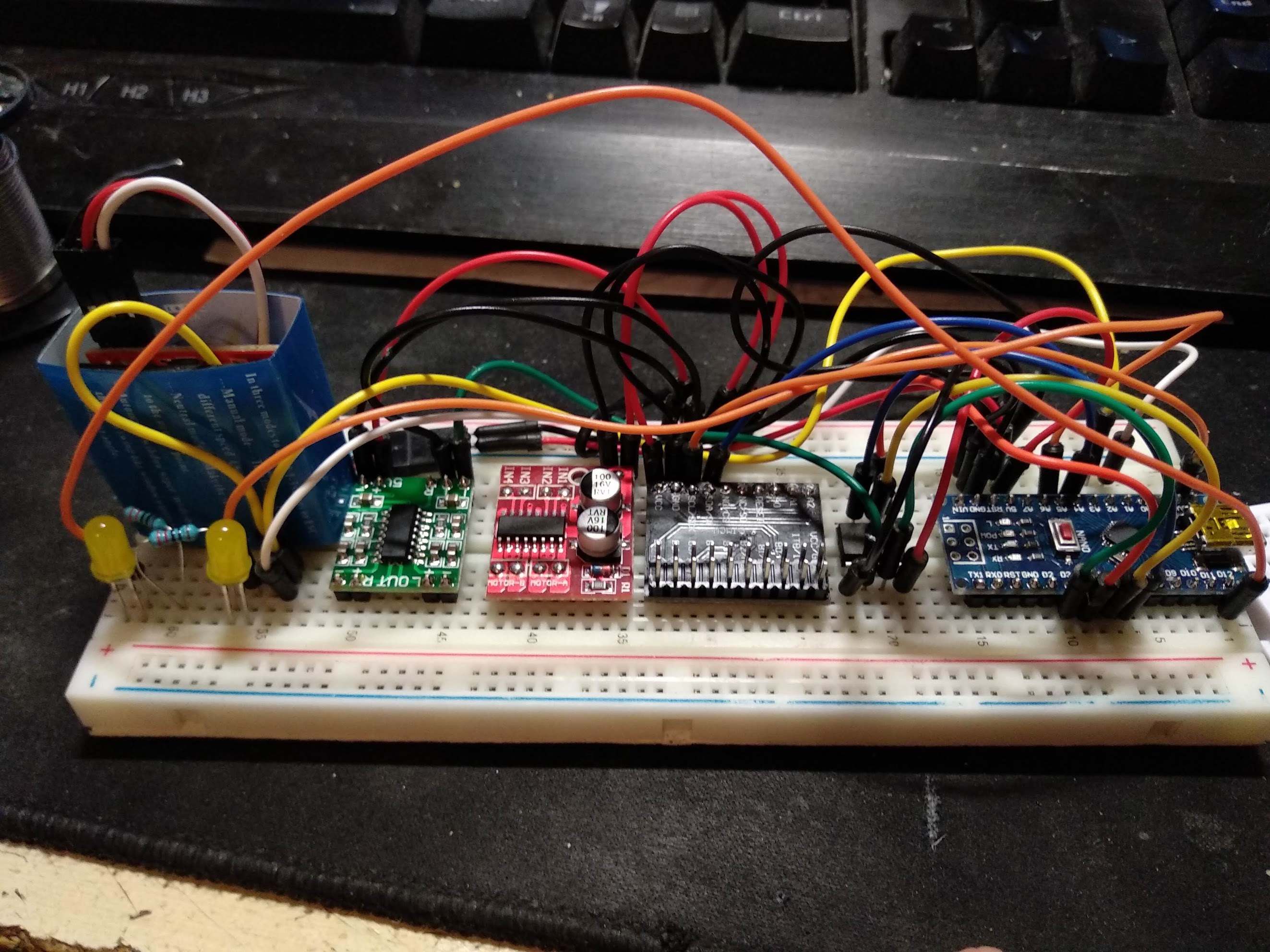
Vyvoj vypada asi takto.
Piny D7-D12 nemuzu pouzit. Neco je blokuje. Hadam, ze neco prijde na vrub preruseni.
Takze mi prakticky na zacatku dosli porty. OK takze dalsi obvod do zapojeni. Pin expander MCP23017 Ten mi prida 16 digitalnich pinu.
A narazil jsem na vtipnou věc. Signál pro generátor beru z pinu A2.
Pokud ale přivedu signál současně na A1 a A3 tak generování zvuku také funguje. WTF?
Re: Arduino
Trošičku se to začíná komplikovat. :D
Re: Arduino
Sem tam sa s Arduinom hram (mas pravdu take zlozite to zasik nie je):
- telemetria (2 moduly jeden v aute s pípakom, druhy nepovinny s displayom) https://www.youtube.com/watch?v=z21juanPS6U
- ovladanie navijaku kvoli 4kanalu https://www.youtube.com/watch?v=L-w2j7OuNFU
- telemetria (2 moduly jeden v aute s pípakom, druhy nepovinny s displayom) https://www.youtube.com/watch?v=z21juanPS6U
- ovladanie navijaku kvoli 4kanalu https://www.youtube.com/watch?v=L-w2j7OuNFU

Re: Arduino
Hele
A nebylo by jednodussi uz raspberry? Nebo jak se to...
Ja s nim treba kropim na hristi a uz ted vidim, jak je to cely mensi nez ten tvuj cernobyl
A nebylo by jednodussi uz raspberry? Nebo jak se to...
Ja s nim treba kropim na hristi a uz ted vidim, jak je to cely mensi nez ten tvuj cernobyl
Re: Arduino
Když bych použil raspi, tak nahradim jen to Arduino nano vpravo.
Pin expander budu stale potřebovat.
H bridge pro obousměrné řízení motoru také.
Audio zesilovače se také nejspíše nezbavím
Možná bych se zbavil černého šwábu digitálního potenciometru.
Ještě budu muset udělat nejaké pole optočlenů nebo tranzistoru.
Když z toho udělám sendvič a tišťak pro rpopojení tak by to nemuselo být tak velké.
BTW. Tohle co vidíš je teď asi za 200kč v HW (včetně nano). K tomu Raspi Zero za 500kč a začíná to být drahá sranda.
Re: Arduino
Po dlouhé době jsem se zase dostal k programování.
Motor stále vrčí
Navijáky by měly být hotovy.
Blinkry blikají.
Teď řeším brzdová světla. Jelikož pin expander neumí PWM a na arduinu jsou všechna přerušení použitá na generování zvuku, tak se asi budu muset naučit softwarove PWM abych pohasnul zadni svetlo.
Zbylá světla by pak měla být snad snadná.
//
SW PWM mi nechtělo fungovat Respektivě rychlost pulzů byla strašně pomalá. Tak jsem znovu prozkoušel piny a jeden s funkčním PWM pro zadní světla jsem našel.
Takže mám funkční pozičku s brzdou. Ještě dopsat kod pro světla zpátečky a zadní světla jsou komplet
Pro přední musím napsat kod pro postupné spínání dalších světel.
Pak už jen pár optimalizací a variantu pro evropské vozidlo mám hotovou.
///Přední světla fungují Takže zbývá už jen zpátečka.
